Shake Simulator
3-Axis Blur Vibration Simulator [TSS Series]
-
TSS-1000
The TSS series is designed to verify the image stabilization functions of digital cameras, camcorders, mobile terminals, and surveillance cameras, including SLR and single-lens reflex cameras, and to reproduce vibrations caused by camera shake, etc. The TSS series is designed to verify the image stabilization functions of various imaging devices. In recent years, cameras with higher magnification and pixel counts have become more and more essential for image stabilization, and this vibration simulator can be used for free vibration waveform driving, which is particularly important.
Features
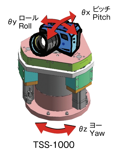
High performance pitch, yaw, and roll
High-response, high-accuracy, high-resolution pitch, yaw, and roll axes are mounted by employing servo motors. Each axis can be driven synchronously.
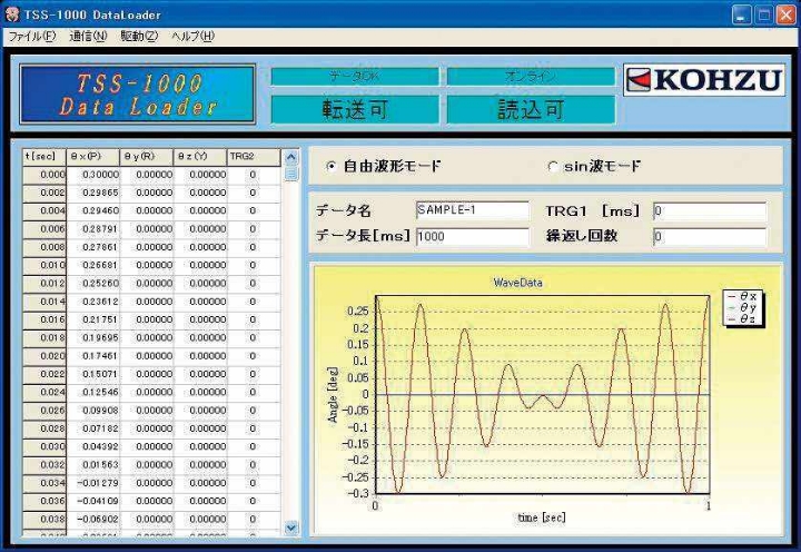
Easy-to-use software
By using the data transfer program 《Data Loader》, drive data such as free waveform, sin wave, composite sin wave, amplitude modulation wave, and frequency modulation wave can be easily transferred to the controller. Free waveform drive can be set for up to 64 seconds, which is plenty of time for analysis. Arbitrary trigger output is also possible.
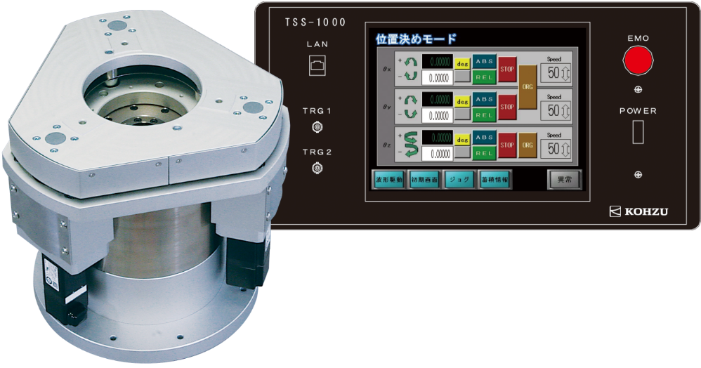
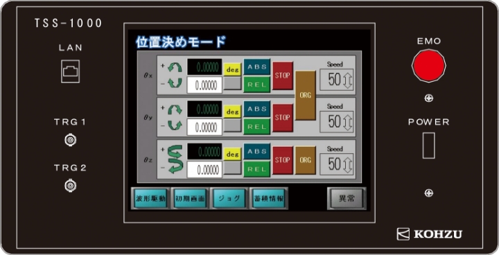
Controller with touch panel
The touch panel makes the controller easy to use. Waveform drive, positioning, and jog operation modes are available, and sin waveform drive can be used without a PC, while complex free waveforms can be used by transferring drive data from a PC. The output of a trigger signal makes it possible to capture images taken under the same vibration conditions with good reproducibility, enabling analysis of shake correction using non-statistical methods, which has been difficult to do in the past.
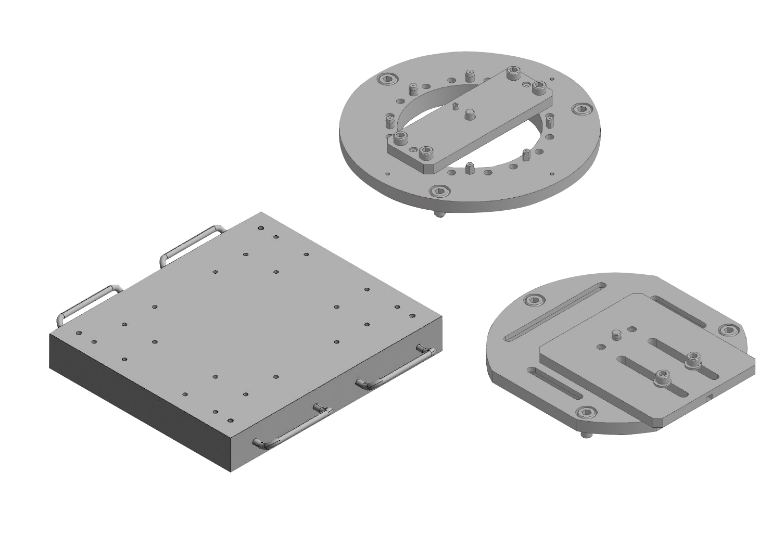
Options
Two types of camera mounting parts are available as hardware options: one with the camera screw positioned at the yaw center, and the other with the camera screw offset in the front-back and left-right directions. A box-shaped surface plate is also available to mount the entire system. As a software option, a data transfer DLL library is available for customers to integrate analysis software.
Mechanical Specifications
| Model | TSS-1000 | |
| Axis configuration | ΘX, ΘY (synchronized with M1 to M3) ΘZ (direct drive motor) | |
| Positioning drive | Minimum instruction unit | 0.00001deg (≈ 0.175μrad ≈ 0.036arcsec) |
| Sinusoidal waveform drive | Frequency | 0.1Hz to 10Hz, set in 0.1Hz increments (5Hz or less if amplitude is greater than ±0.5deg) |
| Amplitude | 0.1deg to 1deg, set in 0.1deg increments (±0.5deg or less if frequency is greater than 5Hz) | |
| Number of operations | Infinite continuous operation | |
| Free waveform driving | Data length | 64 seconds or less |
| Minimum command unit | 0.00001deg | |
| Minimum time unit | 2ms | |
| Number of operations | Number of times to run continuously can be set (1 to 9999 times or infinite times) | |
| Limit of waveform (angle) | θx, θy: ±1deg θz: ±31deg | |
| Waveform limit (other) | (Amplitude)×(Frequency) ≦ 5.9[deg-sec-1] (Amplitude)×(Frequency) 2≦50[deg-sec-2] (Frequency) | |
| Ambient operating temperature | 0°C to 40°C | |
| Ambient operating humidity | 20% to 80% (non-condensing) | |
| Max. mounting load | 19.6 N (2 kgf) | |
| Weight | 27.3Kg (excluding controller) | |
Controller Specifications
| Model | TSS-1000 | |
| Power source | AC100V 50Hz/60Hz | |
| Power consumption | 700VA (in normal operation) | |
| Trigger signal (common to 1 and 2) | Output method | Transistor, open collector, sink output |
| Output withstand voltage | DC24V | |
| Output current | 100mA (Maximum) | |
| Output terminal | BNC | |
| Trigger 1 signal cycle | 20% to 80% (no condensation) | |
| Trigger 2 signal | 19.6 N (2 kgf) | |
| Communication | Ethernet 100Mbps | |
| Weight | 20kg (not including stage) | |
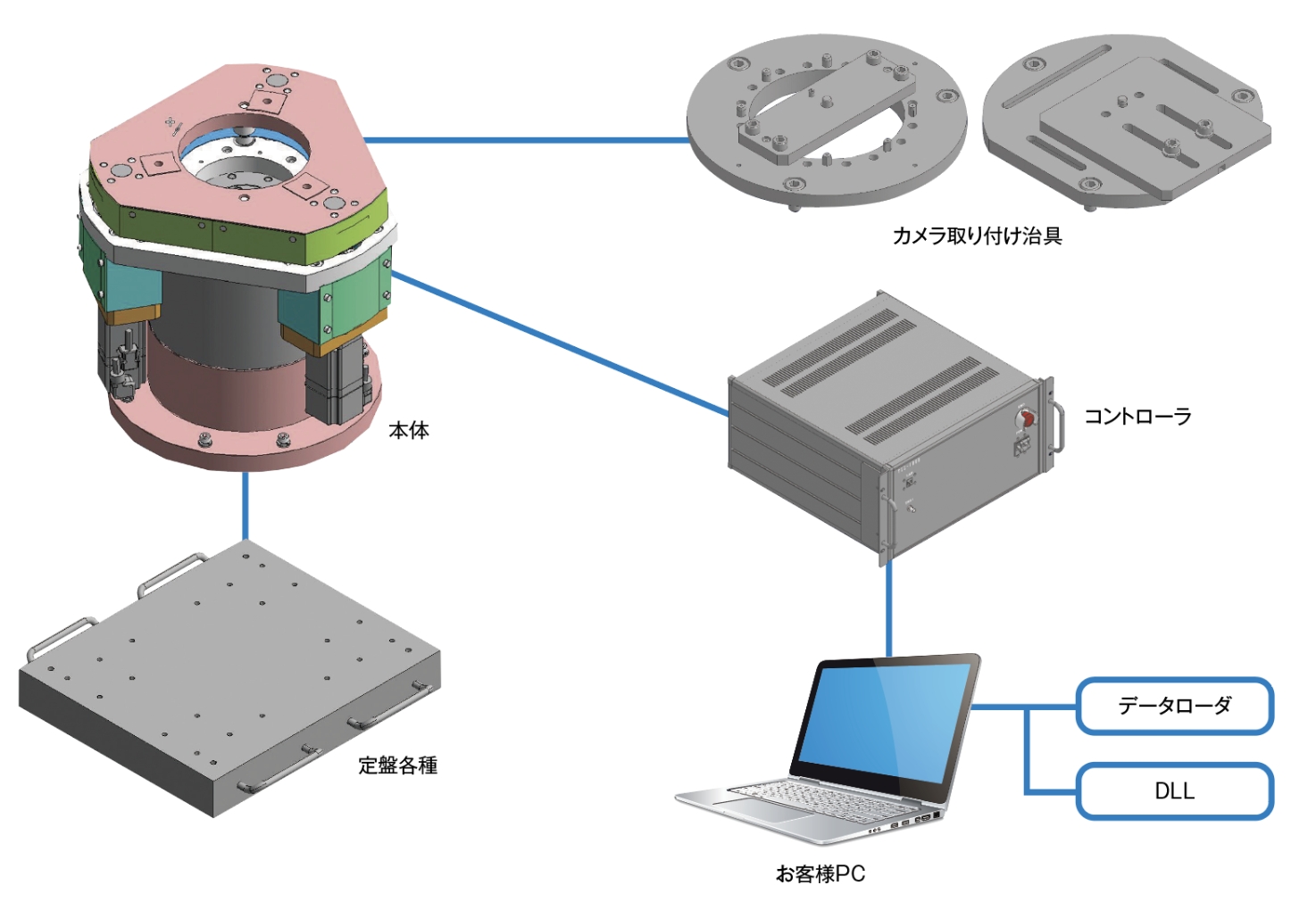
System Configuration
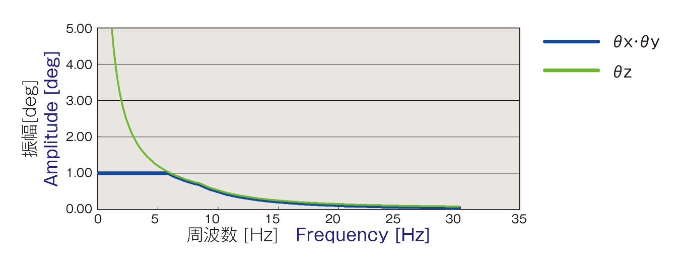
Free Waveform Data & Maximum Amplitude
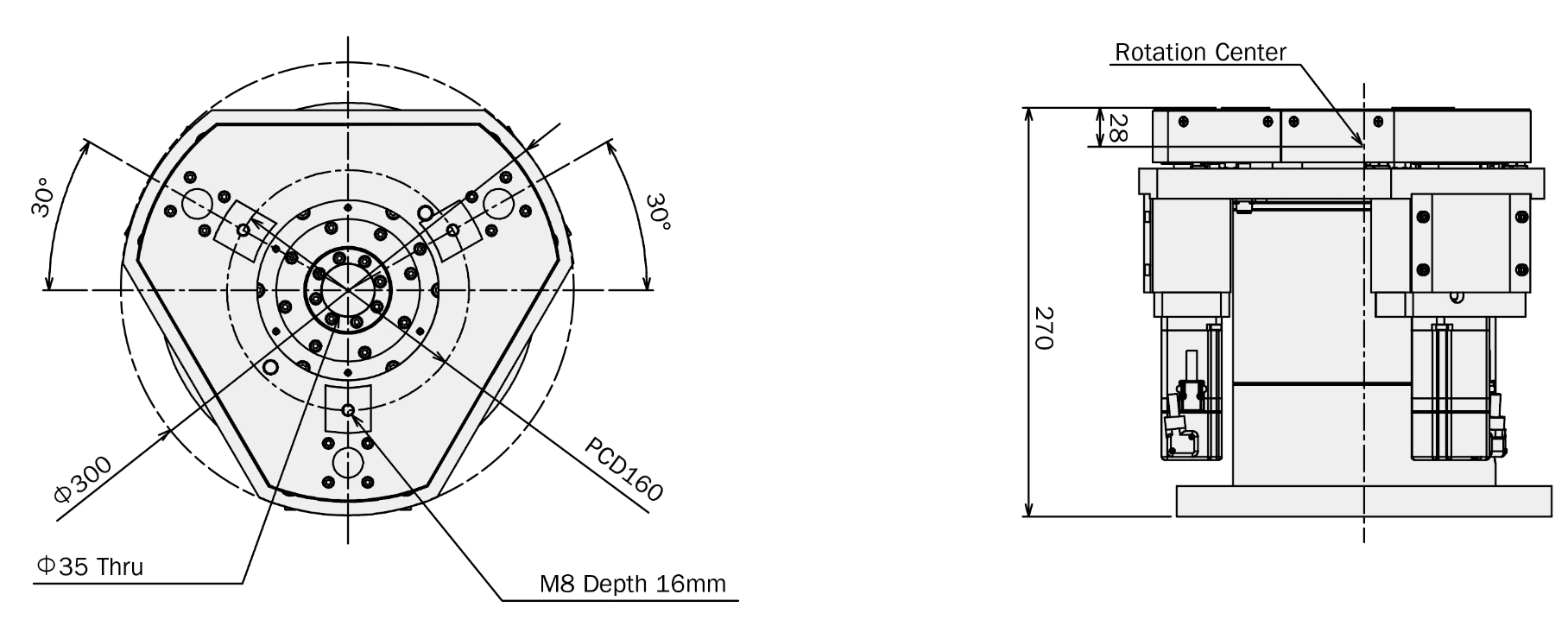
Dimensions