Features of DY-3001YM
-
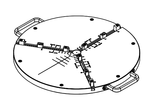
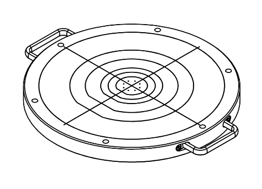
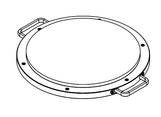
Various measurement devices that can accommodate up to 300 mm square measurement areaVarious Work Tables
We already offer optional work tables that can measure square samples up to 300mm in size and 12inch wafers. In addition to the work tables listed below, we can also design and manufacture custom-made work tables, so please contact us for more information.
Work tables available for immediate selection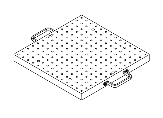
-
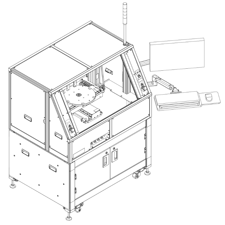
Safety measures are standardSafety Measures (Enclosure Cover)
As a safety measure for the machine, the machine body is equipped with a metal machine cover and a light curtain as standard safety measures, as well as a warning lamp to indicate the machine status. The wall surface of the device cover can be changed to transparent acrylic.
-
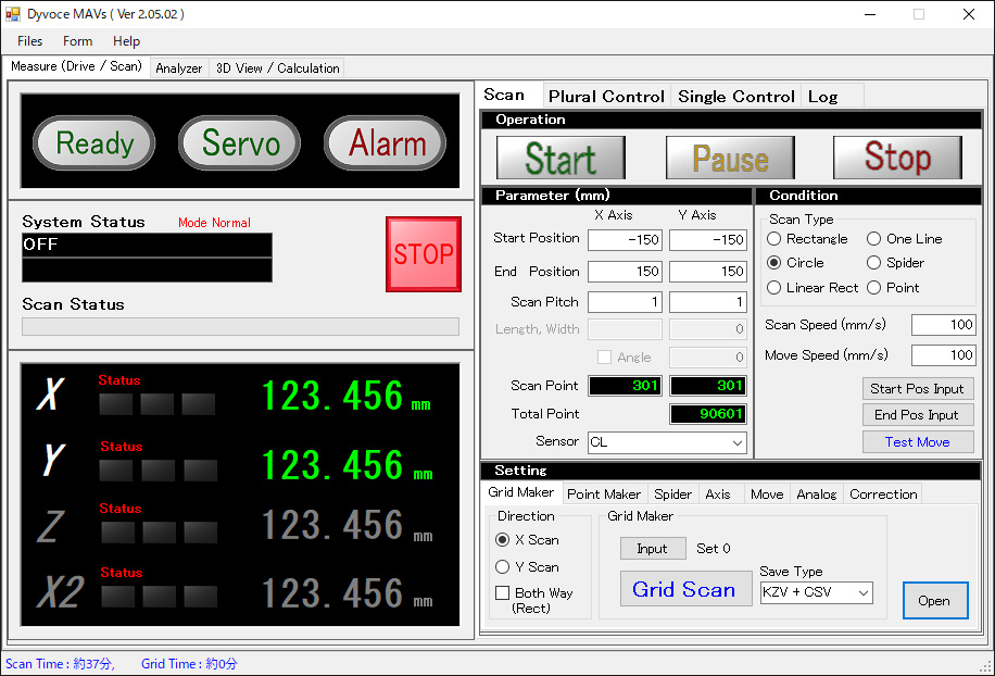
Measurement Software
The control and drive software DyvoceMeasure, which has a wide range of measurement drive functions, enables measurement patterns to be realized with a wide range of drive and measurement functions, including stage positioning. Data can be saved in dedicated analysis software format and CSV format.
-
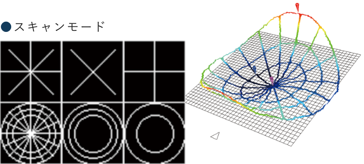
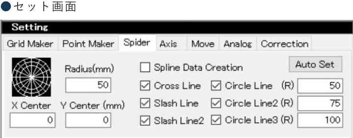
Thinning Measurement
Various scan measurements on the cross line, incline, circle, or a combination of the above are used to create a drive pattern for thinning measurement and measure the surface profile in an approximate manner. This is an overwhelming reduction in measurement time compared to full surface scanning.
-
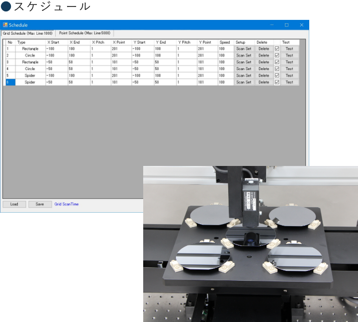
Batch Measurement of Multiple Workpieces (Grid Maker)
Measurement of multiple workpieces is performed as a series of sequences using various combinations of workpiece geometry, measurement parameters, and placement. Individual data for each set program is saved sequentially.
-
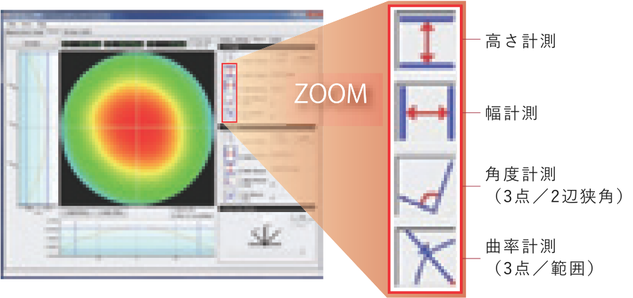
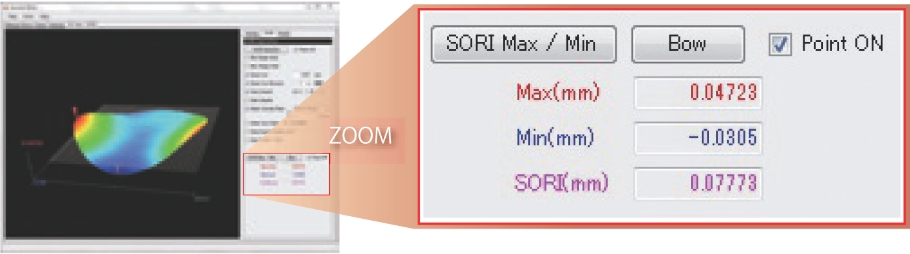
Analysis Software
Various measurements such as 2D/3D cross-sectional profiles using measurement data and various analyses such as “SORI,” “Bow,” “Warp,” and “GBIR” of SEMI standards can be performed, and export to CSV file and report output convenient for report creation are also available.
Shape MeasurementSkew Correction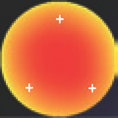 Fulcrum (Coordinate Axis Rotation)
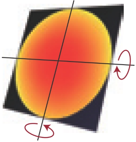
-
Self-weight Deflection Correction
By using the measurement data to correct deflection caused by the wafer's own weight, the original deflection data of the wafer can be calculated. This is especially effective for thin wafers and large diameter wafers.
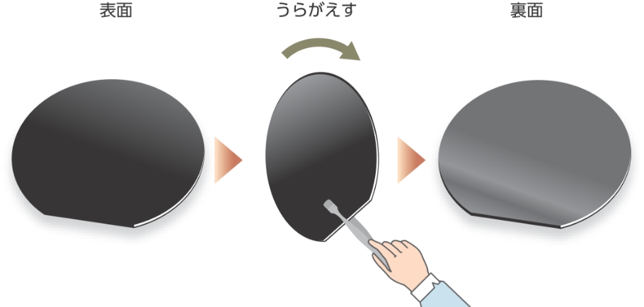
Double-sided Differential Mode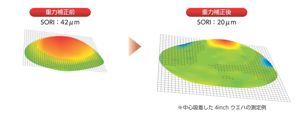 Ideal Model Difference Mode
The surface profiles of the back and front surfaces of a wafer are measured, and the difference of the data is used to create correction data that eliminates the effect of self-weight deflection.
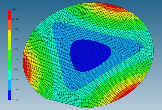
Correction data is created by subtracting the measured data from an ideal model of the wafer created by the finite element method, which includes self-weight deflection, to eliminate the effect of self-weight deflection.
-
Correction using a reference gaugeCorrection using a reference plane substrate (Mapping Correction)
The surface height data of a reference flat substrate is measured in advance and used as correction data. By subtracting the correction data from the actual workpiece measurement data, the minute oscillations of the scan stage are compensated and brought closer to the true value of the workpiece. This is especially effective for measuring workpieces with small warping.
Reference Plane Substrate Measurement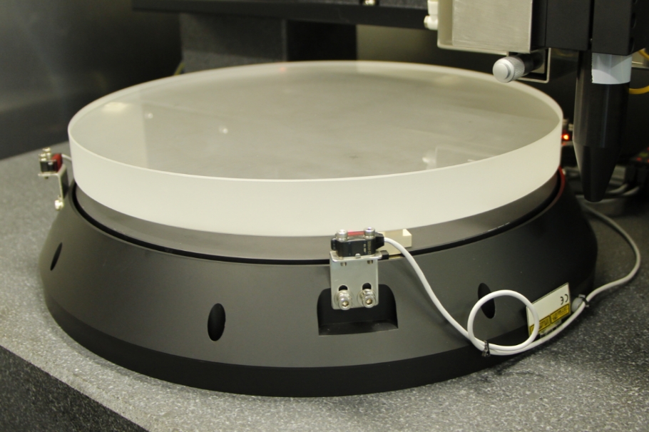
-
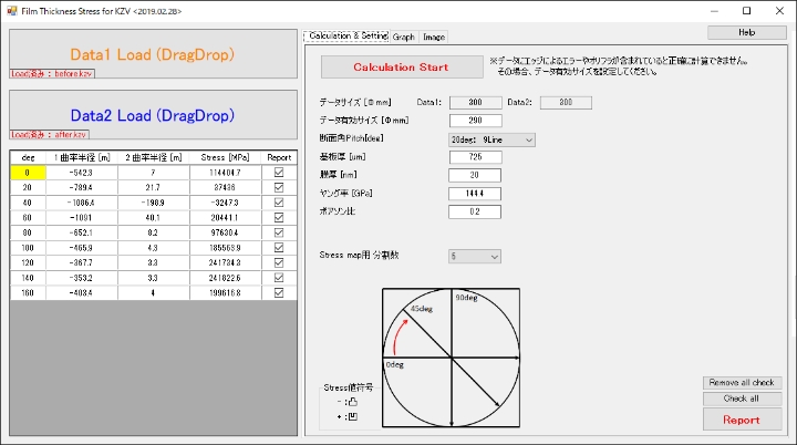
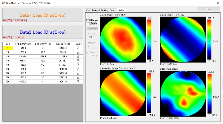
Post-deposition stress measurement application (optional)Measurement Software for Film Stress Distribution
Using SORI profile measurement data before and after deposition, the software specifies analysis lines with respect to the wafer diameter direction and calculates the film stress distribution according to the radius of curvature and set parameters for each data. The software also calculates profile data for each cross-section and outputs a report.